General
Up to three potential-free alarm buttons can be connected to the NRT.
Alternatively, up to two voltage-activated inputs can be used for connecting alarm buttons.
Either the normally closed (NC) or normally open (NO) contacts of the alarm buttons can be used. The desired contact type is set via a slide switch for each input. The factory default setting is normally open (NO).
Unused inputs for alarm buttons must always be configured as normally open (NO)!
Connect potential-free alarm button to SM 1
An alarm button can be connected directly to the speaker module. The switching behaviour of the button (NO/NC) can be set using the corresponding slide switches on the alarm device. Ensure that the wiring from the alarm button is kept as short as possible and connected directly to the speaker module without any detours.
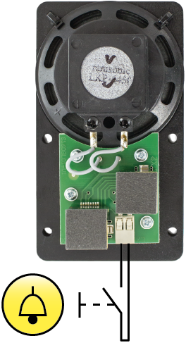
Maximum length of the alarm button lead to SM 1: < 0.5 m!
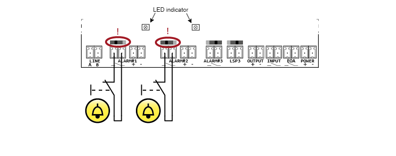
Connect potential-free alarm buttons to NRT XT
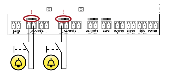
Caution:
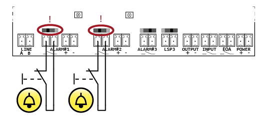
When using buttons with normally closed (NC) contacts, the corresponding slide switch must be set accordingly (see connection example).
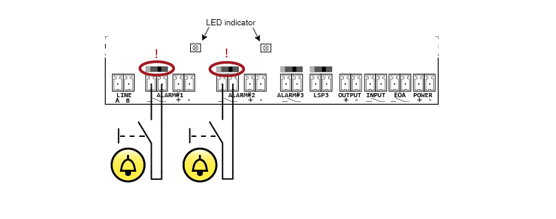
Voltage-activated inputs on the NRT XT
In addition to the potential-free inputs, the NRT provides two voltage-activated inputs (12–24 V DC) for triggering an alarm. These inputs eliminate the need for a coupling relay in many lift installations, allowing existing alarm buttons of the system to be connected to the alarm device without galvanic isolation.
For simple and quick function monitoring, yellow LEDs are located directly above the corresponding screw / plug-in terminals. An LED lights up when the corresponding input is active. The contact type (normally open or normally closed) can be configured using the slide switches.
Example: Alarm buttons with normally open (NO) contact:
Example: Alarm buttons with normally closed (NC) contact:
Caution:
The alarm buttons must remain functional even in the event of a power failure of the lift system!
When using the voltage-activated inputs, the switched voltage must be buffered!