Breadcrumbs

Connections and Controls


Anschlüsse und Bedienelemente.drawio.png

1

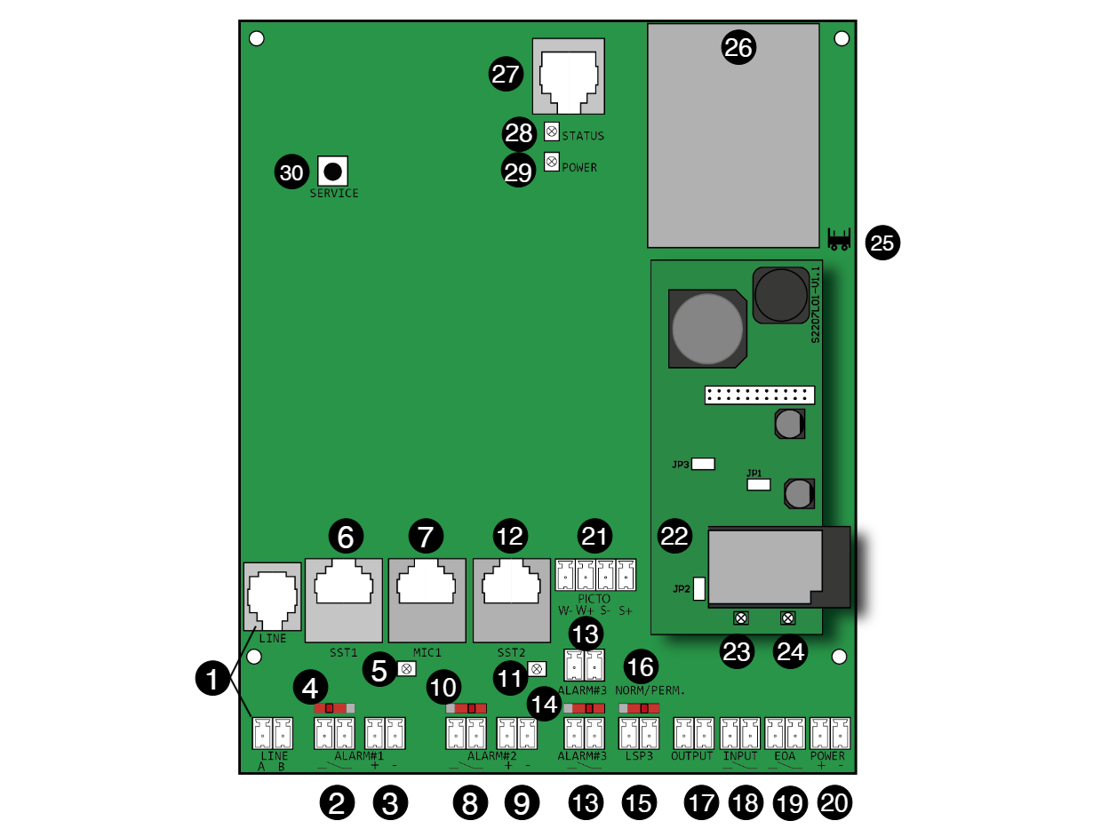
Screw / plug-in terminal (non-polarised) or RJ12 socket for the telephone/bus line (FXO)

2

Screw / plug-in terminal ALARM#1, potential-free.
Connection for the alarm button of intercom station 1.

3

Screw / plug-in terminal for voltage-activated alarm button input ALARM#1.
Alternative connection for the alarm button of intercom station 1.
+ = 12–24 V DC
– = GND

4

Switching behaviour of alarm button input ALARM#1
Schiebeschalter 2.png = ALARM#1 button set as NO (normally open)
Schiebeschalter 1.png = ALARM#1 button set as NC (normally closed)

5

Indicator LED for the voltage-controlled alarm button input ALARM#1.
The LED lights up when voltage is present.

6

RJ45 socket SST1 for external voice units SM 1, SM 2, and DLS 1.

7

RJ45 socket MIC1 for external microphones of type MK 1 to MK 4.

8

Screw / plug-in terminal ALARM#2, potential-free.
Connection for the alarm button of intercom station 2.

9

Screw / plug-in terminal for voltage-activated alarm button input ALARM#2.
Alternative connection for the alarm button of intercom station 2.
+ = 12 - 24 V DC
- = GND

10

Switching behaviour of alarm button input ALARM#2
Schiebeschalter 2.png = ALARM#2 button set as NO (normally open)
Schiebeschalter 1.png = ALARM#2 button set as NC (normally closed)

11

Indicator LED for the voltage-controlled alarm button input ALARM#2.
The LED lights up when voltage is present.

12

RJ45 socket SST2 for external voice units SM 1, SM 2, and DLS 1.

13

Screw / plug-in terminal ALARM#3, potential-free.
Connections for the internal and the alarm button located beneath the car, potential-free.
Both connections are wired in parallel.

14

Switching behaviour of alarm button input ALARM#3
Schiebeschalter 2.png = ALARM#2 button set as NO (normally open)
Schiebeschalter 1.png = ALARM#2 button set as NC (normally closed)

15

Screw / plug-in terminal LSP
Connection for the internal speaker.

16

Slide switch NORM / PERM.
The switch defines whether the internal loudspeaker operates as a central loudspeaker (switch position PERM) or is used only for a single intercom station.

17

Screw / plug-in terminal OUTPUT
Connection for the configurable output. The output voltage corresponds to the voltage applied to the POWER terminal.

18

Screw / plug-in terminal INPUT, potential-free.

19

Screw / plug-in terminal EOA “End of Alarm”, potential-free.

20

Screw / plug-in terminal POWER
Connection for the operating voltage 12–24 V DC.

21

Screw / plug-in terminal PICTO
Polarity-dependent connection for the pictogram indicators “Please wait” and “Please speak”.
W– = Negative terminal for pictogram indicator “Please wait”
W+ = Positive terminal for pictogram indicator “Please wait”
S– = Negative terminal for pictogram indicator “Please speak”
S+ = Positive terminal for pictogram indicator “Please speak”

22

WEM module
Provides Wi-Fi connectivity.

23

LED “WEM module active”

24

LED “Wi-Fi network active”

25

Socket for battery

26

Battery 3,6 V / 800 mAh

27

Socket TERMINAL
Connection socket for programming device PRG 100 or programming cable PRK.

28

LED „STATUS“
Indicates the current device status.

29

LED "POWER"
Indicates the status of the power supply.

30

Service-Button