|
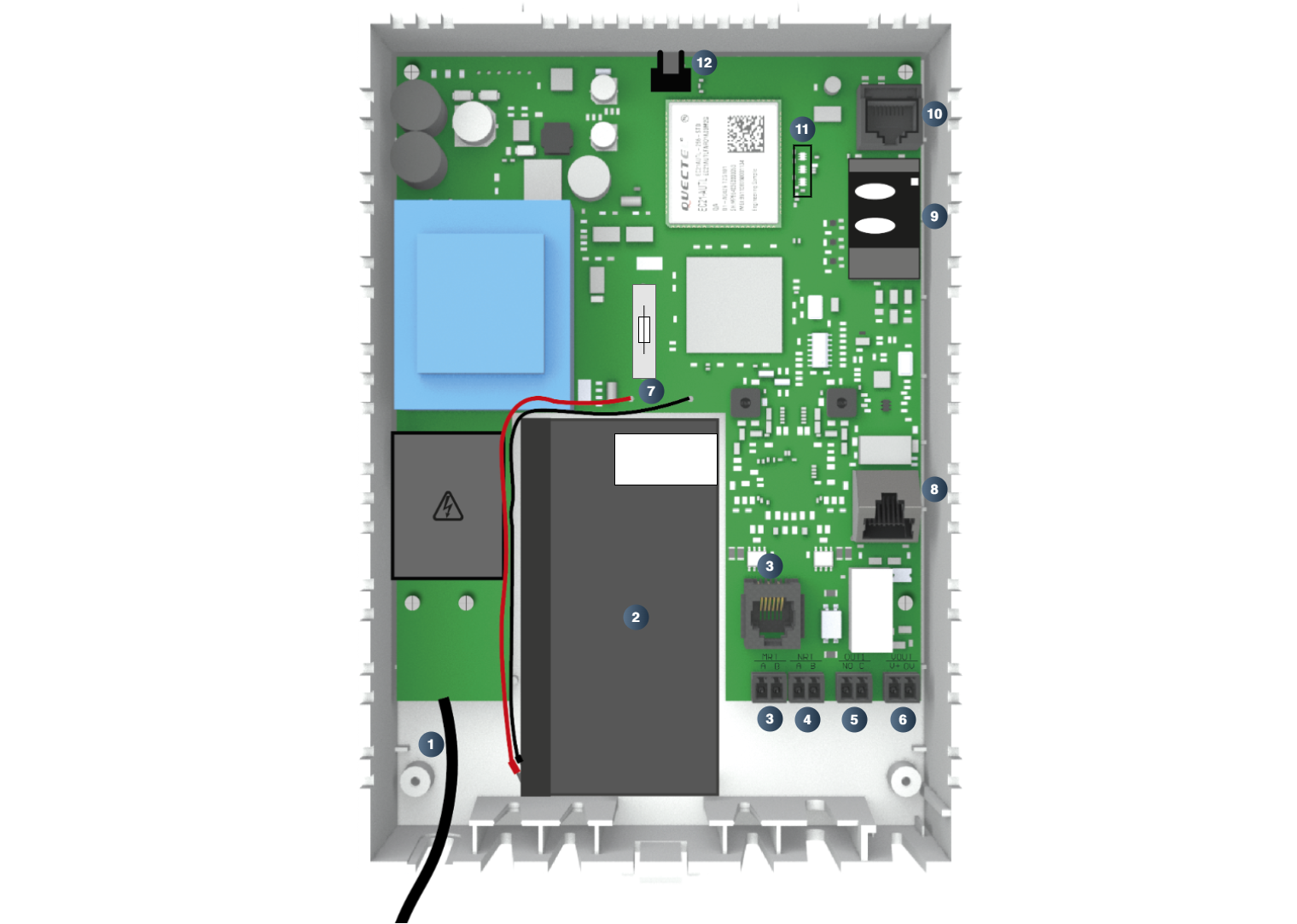
1 |
Power cable |
|
2 |
|
|
3 |
MRT connection The IPG includes an integrated machine room intercom function. A machine room telephone must be installed and connected either to the MRT terminals or to the corresponding RJ12 socket. |
|
4 |
NRT connection The 2-pin terminal provides the analog a/b port for the alarm device. Polarity of the a/b port "NRT" does not need to be observed. |
|
5 |
OUT 1 connection Output is used to signal an IPG error to an external alarm unit. For example, an elevator can be shut down if the lift alarm can no longer be ensured due to a 4G network failure. Output “OUT 1” is implemented as a potential-free switching contact and can be operated in normally closed (NC) or normally open (NO) mode. |
|
6 |
VOUT connection The terminals V+ / 0V provide the power supply for an alarm device.
|
|
7 |
Fine-wire-fuse and battery connection cables |
|
8 |
LAN connection (only for IPG 141-003) A computer can be connected to the LAN interface to configure the IPG via the integratet web interface. In addition, elevator components can be connected via the LAN interface to cloud services (e.g. those of component manufacturers) using the IP protocol. |
|
9 |
Slot für SIM-Card Slot for a standard 2FF SIM card. The SIM card is installed at the factory and only needs to be activated. Observe the instructions on the packaging and on the device housing.. |
|
10 |
Terminal socket Socket for connecting the programming cable (PRK) or the programming device PRG100. |
|
11 |
|
|
12 |
SMA antenna connector |