Pictogram indicators according to EN 81-28:2022 can be connected via the corresponding “PICTO” terminals.
They are then controlled in addition to the LEDs integrated in the device.
The terminal designations are:
|
YE |
0 V, switched. For the yellow pictogram indicator, max. 100 mA |
|
V + |
+12 V to +24 V, depending on the supply voltage |
|
GN |
0 V, switched. For the green pictogram indicator, max. 100 mA |
|
V + |
+12 V to +24 V, depending on the supply voltage |
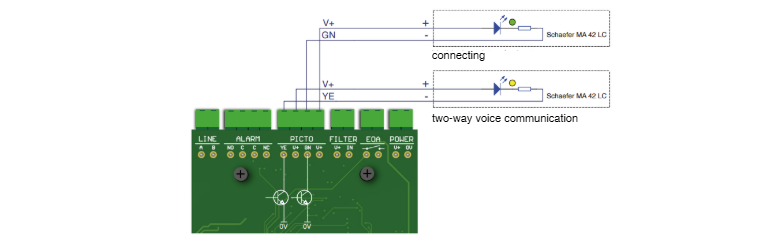
Connection example:
Important:
Unlike previous NT/XT/XS devices, the pictogram indicators of this model are supplied directly with voltage.
V+ carries the NRT supply voltage (12–24 V DC) continuously, while GND is switched.
The outputs must not exceed 100 mA.
The correct function of the pictogram indicators can be tested using a PRG 100:
-
Connect the PRG 100 to the alarm device via the “Terminal” socket.
-
Switch on the PRG 100 by pressing and holding the “✅” button.
-
Press the service button at NRT.
-
Wait until the device type and software version are displayed on the PRG screen.
-
Press the “+” button repeatedly until “SETTINGS?” appears on the display, then confirm with “✅”.
-
Use the “+” button to navigate to submenu “OUTPUTS”.
-
In the “OUTPUTS” menu, scroll with “+” to the test menu “Output PICTO” and confirm
with “✅”. -
Use the “+” and “–” buttons alternately to activate the pictogram outputs for yellow and green pictogram indicators.