|
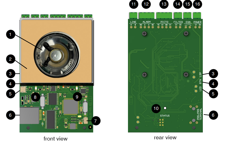
1 |
Speaker |
|
2 |
Adhesive pad with protective film |
|
3 |
Speaker connector.
|
|
4 |
Connector for the alarm button integrated in the optionally available stainless-steel front panel. |
|
5 |
Connector for the alarm button integrated in the optionally available stainless-steel front panel. |
|
6 |
Connector TERMINAL
|
|
7 |
Microphone connector.
|
|
8 |
LED for the yellow pictogram indicator “connecting” |
|
9 |
LED for the green pictogram indicator „two-way voice communication“ |
|
10 |
Status LED |
|
11 |
Screw / plug-in terminal (non-polarised) or RJ12 socket for the telephone/bus line (FXO) |
|
12 |
Terminal ALARM,
|
|
13 |
Terminal PICTO
|
|
14 |
Screw / plug-in terminal FILTER, potential-free. |
|
15 |
Screw / plug-in terminal EOA “End of Alarm”, potential-free. |
|
16 |
Screw / plug-in terminal POWER
|